Yonjou Vacuum Assisted Priming Pump / Diaphragm Vacuum Pump for Wellpoint or Dewatering Priming System
Basic Info.
| Model NO. | DPP25 |
Product Description
Applications:
The diaphragm vacuum pump is a key part of the priming system. Its function is to remove air and create a vacuum at the pump suction port while the centrifugal pump input shaft is rotating.
The YONJOU Pump Priming System with is designed to allow the pump to prime without using a foot valve and without manually adding water to the system.
lWater & waste water
lConstruction & civil engineering
lOil & Gas
lMining
lMarine
lMunicipal
lIndustrial
Features:
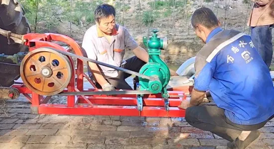
The vacuum pump drive system consists of a drive pulley on the main pump drive shaft, a rubber drive belt, and a drive pulley attached to the vacuum pump drive shaft.
The vacuum pump creates a vacuum in the priming chamber that causes liquid to enter the priming chamber and suction port of the centrifugal pump.
As the liquid level rises in the priming chamber and the centrifugal pump casing, the ball begins to float on the liquid and move the linkage and valve stem upward. Moving upward, the linkage allows the peel valve to force close the breath seat. With the valve closed, the vacuum pump stops pumping air and begins to coast. No liquid can pass the valve and enter the vacuum pump.
Vacuum Pump Specifications
Size | 25mm |
Output | 50CFM (23.6L/s, 85m3/h) |
Suction Priming Lift Head | -8.5m |
Operation Speed | 1500 rpm |
Power Requirement | 4 kW |
Theory of Operation:
The vacuum pump is a key part of the priming system. Its function is to remove air and create a vacuum at the pump suction port while the centrifugal pump input shaft is rotating.
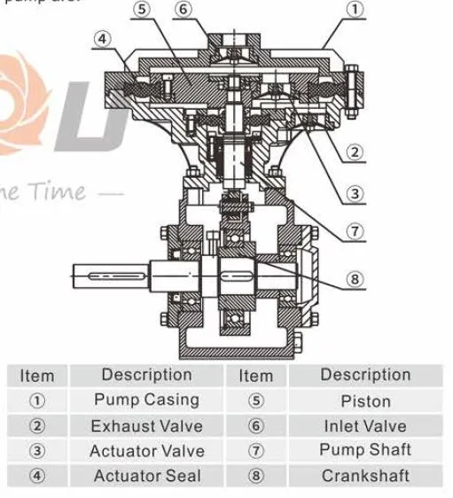
As viewed from its drive pulley, the vacuum pump rotates in a clockwise direction in order to evacuate air from the vacuum pump system. The air flow through the pump is through the inlet nozzle, passing the inlet valve, past the actuator valve at the center of the shaft, through the exhaust valve, and out the exhaust nozzle.
With the pump drive pulley operating from the 12 o'clock position, the crankshaft force the piston in a upward direction. Increasing air pressure in upper chamber and opens the actuator valve. Air is allowed to flow into the down chamber of the pump casing (below the piston) until the drive pulley reaches the 6 o'clock position.
From the 6 o'clock position, the piston rod and crank force the piston in an downward direction. Increasing air pressure in down chamber, opens the exhaust valve and forces the actuator valve closed. Air is then pushed out of the area below the piston and through the exhaust valve until the drive pulley again reaches the 12 o'clock position.
At the same time, as the piston is pushed downward, a vacuum is created in the upper chamber of the pump casing (above the piston).
The vacuum pulls the inlet valve open, and air flows into the pump past the inlet valve.
This cycle repeats itself until the inlet of the pump is closed either by the valves in the priming chamber or by closing the ball valve on top of the priming chamber. In the "closed" condition, no air enters the vacuum pump. The inlet valve, the piston valve, and the exhaust valve all remain closed.
Without air entering the pump, minimal vacuum is created below the piston on its upstroke, so the inlet valve remains closed. Air flow is stopped through the pump. The pump can idle in this manner indefinitely or until a demand is made on it to again evacuate the system.
Dimension:
Construction:
1 | Inlet valve | 8 | Oil seal | 15 | Bearing |
2 | Pump upper cover | 9 | Bush | 16 | Outlet valve |
3 | Bolt | 10 | Pump body | 17 | Actuator valve |
4 | Upper piston plate | 11 | Pin | 18 | Piston rod |
5 | Big diaphragm | 12 | Bearing | 19 | Bearing house |
6 | Down piston plate | 13 | Drive shaft | 20 | Crank sleeve |
7 | Small diaphragm | 14 | Eccentric sleeve | 21 | Bearing |


